 English



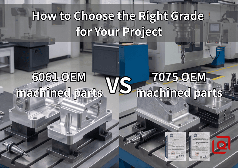
Stop picking your aluminum spec off a generic internet cheat sheet. When you're dropping $80,000 on a 500-piece OEM structural run for aerospace mounts or downhole hydraulic manifolds, the raw yield strength delta between 6061-T6 and 7075-T651 isn't just a design option—it’s the boundary line between smooth 12,000 RPM chip-evacuation and total spindle stall from work-hardening deflection.
Let's cut through the standard marketing fluff.
+------------------------------------+-----------------------+-----------------------+
| Mechanical & Thermal Property      | 6061-T6 (UNS A96061)  | 7075-T651 (UNS A97075)|
+------------------------------------+-----------------------+-----------------------+
| Ultimate Tensile Strength (MPa)    | 310                   | 572                   |
| Yield Strength (MPa)               | 276                   | 503                   |
| Brinell Hardness (500 kg, 10mm)    | 95                    | 150                   |
| Thermal Conductivity (W/m·K)       | 167                   | 130                   |
| Machinability Index (100 = 2011-T3)| 50%                   | 70%                   |
| Fracture Toughness (MPa·m¹/²)     | 29                    | 24 (L-T direction)    |
| Anodizing Layer Density (Class II) | High (Clear Uniform)  | Low (Silvery/Grayish) |
+------------------------------------+-----------------------+-----------------------+
1. Metallurgical Realities: Silicon-Magnesium Matrix vs. Zinc-Copper Strain
Look under the hood. 6061 is an Al-Mg-Si ternary alloy hardened by Mg₂Si precipitate phase. 7075 relies on a volatile Al-Zn-Mg-Cu system where η-phase (MgZn₂) and T-phase (Al₂Mg₃Zn₃) disperse along grain boundaries.
Why care on the shop floor?
Because copper content in 7075 (1.2–2.0 wt%) wrecks weldability and Tank 4 sulfuric acid anodizing bath performance, while giving you brutal shear strength. Try TIG welding a 7075 mounting flange to a 6061 chassis frame—liquation cracking in the heat-affected zone (HAZ) will tear the fillet weld apart before the part cools below 200°C.
-
6061-T6: Outstanding fatigue endurance limit (96 MPa at 500 million cycles). Ideal when your CNC-milled OEM casing endures cyclical hydraulic shock loads without structural strain-aging.
-
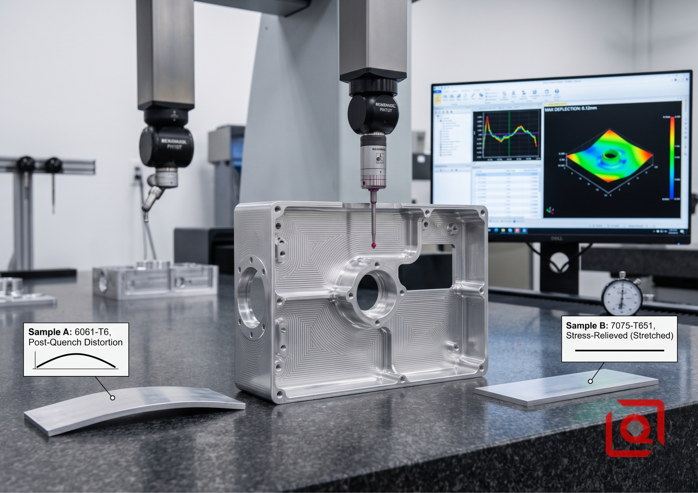
7075-T651: Stress-relieved by stretching 1.5%–3.0% post-solution heat treatment. Eliminates the dreaded "banana effect" when deep-pocket roughing at 18,000 RPM on a 5-axis machine, keeping flatnesses within 0.015 mm per 300 mm span.
2. Chip Formation, Tool Wear, and Feeds & Speeds
Don't run them with the same feeds.
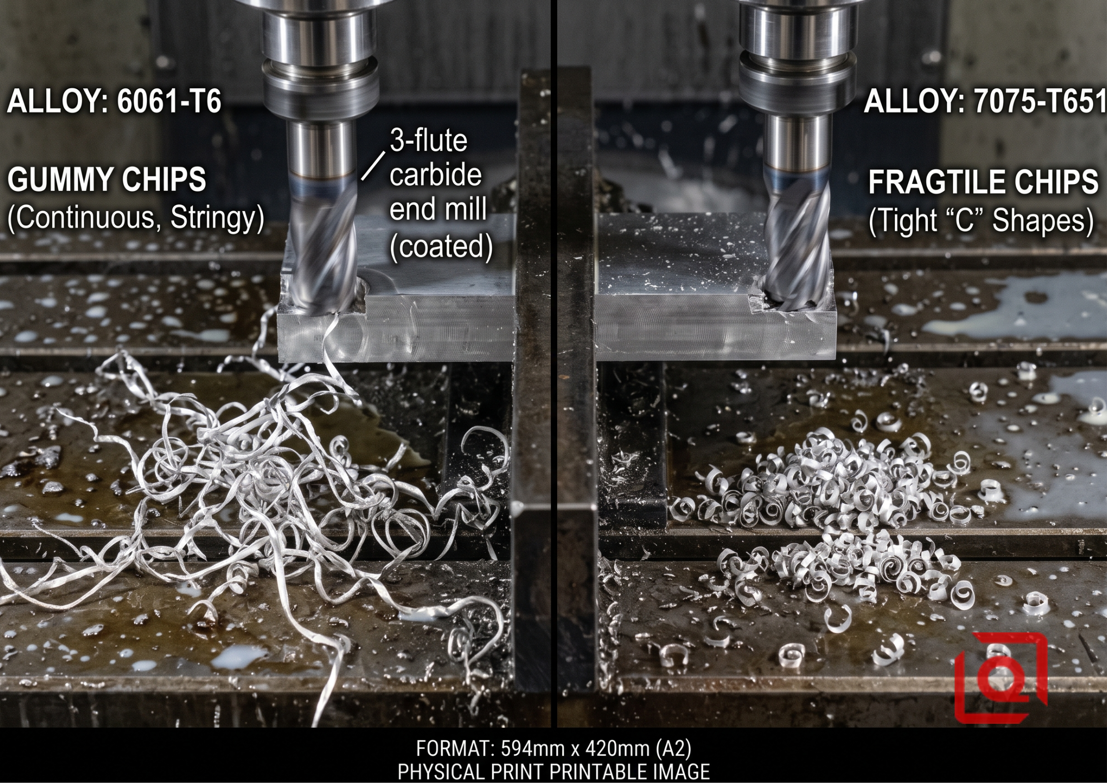
6061 is gummy. If your coolant concentration drops below 7.5% Brix during high-speed trochoidal milling, expect Built-Up Edge (BUE) on your 3-flute uncoated carbide end mills within 12 minutes of cut time. The aluminum welds itself to the rake face, spikes cutting force by 45%, and snaps the tool shank inside a $4,000 blind pocket.
7075, conversely, shears like dense hardwood. It breaks chips into tight, manageable "C" shapes. But its 150 Brinell hardness tears through PVD TiB₂ (Titanium Diboride) coatings faster if cut temperatures breach 380°C.
Step 1: Check billet heat-lot certification (AMS 4027 for 6061-T6; AMS 4045 for 7075-T651).
Step 2: Calculate maximum chip load (fz) based on radial engagement (ae).
Step 3: Dial in high-pressure coolant (minimum 70 bar / 1,000 PSI) through the spindle center.
Step 4: Execute roughing paths using dynamic trochoidal milling; avoid dwell points.
Step 5: Inspect first-article dimensions on CMM after thermal stabilization at 20°C.
When slotting solid 7075 blocks with a 12mm 3-flute ZrN-coated end mill:
-
Vc (Cutting Speed): Push to 450 m/min.
-
fz (Feed per Tooth): Keep at 0.08 mm/tooth.
-
Observation: Drop the feed by 20% on 6061 to prevent chip packing inside the tool flutes, or raise coolant pressure to blow stringy ribbons out of deep cavities.
3. Machining Distortion: The Internal Stress War
Here is where real OEM production fails: stress relief.
A client sent us CAD files for an OEM thin-walled optical chassis—wall thickness 1.2 mm, total length 450 mm. They insisted on 6061-T6 to cut raw material costs by 38%.
The result? Uncontrolled bow distortion. Once we cleared 70% of the core material, residual quench stresses in standard T6 stock pulled the thin sidewalls inward by 0.68 mm, completely ruining the tight ISO 2768-mH tolerance.
Raw Billet Residual Stress -> Asymmetrical Material Removal -> Unbalanced Elastic Recovery -> Dimensional Failure
To fix this on 6061:
-
Rough cut leaving 0.8 mm stock everywhere.
-
Unclamp from the fixture completely to allow elastic recoil.
-
Perform stress-relief aging at 175°C for 5 hours, or re-spec the bill of materials to 7075-T651 (plate material pre-stretched per ASTM B209).
-
Re-clamp using custom vacuum fixtures or low-melting-point bismuth-alloy matrix jaws.
-
Finish-machine at light axial depths of cut (ap = 0.2 mm).
4. Surface Treatments: Anodizing, Corrosion, and MIL-Spec Compliance
If your OEM assembly operates in marine or harsh chemical environments, 7075 can betray you through Stress Corrosion Cracking (SCC) along the short-transverse (ST) grain direction.
-
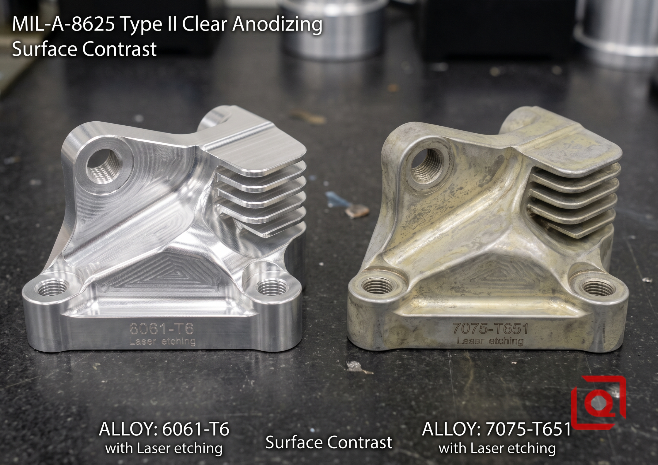
MIL-A-8625 Type II Clear Anodizing: 6061 yields a crystal-clear, highly reflective oxide layer (15–25 µm thick). 7075 turns a muddy, yellowish-grey due to high copper and zinc intermetallic phase interference in the electrolyte bath.
-
Type III Hardcoat (50 µm): 7075 reaches up to 550 HV microhardness, making it perfect for sliding OEM actuator pistons—provided you lower the anodizing bath temperature to 0°C–2°C and ramp current density at 3.5 A/dm² to prevent microscopic burnt edges.
FAQs
Q1: Why did my 7075-T651 part crack along the internal corner radii during high-pressure hydraulic testing?
A: You likely spec’d an aggressive internal fillet radius (R < 0.5mm) without accounting for the notch sensitivity of 7075 (Kt stress concentration factor spikes past 2.8). Unlike 6061, 7075 has lower fracture toughness (24 MPa·m^{1/2} vs 29 MPa·m^{1/2}). Increase internal corner radii to at least 1.5mm (20% of tool diameter) or specify a 150° T73 heat treatment (e.g., 7075-T7351) to relieve intergranular SCC susceptibility before pressure cycling.
Q2: Can I clear-anodize 6061-T6 and 7075-T651 in the same bath to reduce OEM finishing costs?
A: Absolutely not. 7075 contains 1.2-2.0wt% copper, while 6061 holds less than 0.4wt%. Processing them in the same sulfuric bath (180 g/L H₂SO₄}_4$ at 20℃ causes copper ions from 7075 to bleed into the solution. This leads to galvanic burning, uneven film growth, and a muddy grey hue on the 6061 components. Always segregate anodizing runs per alloy matrix.
Q3: How do I prevent thread stripping in 6061-T6 OEM aluminum housings under dynamic torque?
A: 6061’s shear strength (207 MPa) is insufficient for direct M5+ threads under cyclic tensile loading exceeding 12Nm. Never rely on tapped raw threads for structural fastenings. Always specify Helicoil STI inserts or Keysert (Keensert) stainless steel inserts per NASM 8846. Ensure engagement length is at least 2.0×nominal diameter to distribute thread load evenly across the softer matrix.
Q4: Which alloy should I select for OEM optical housing components requiring sub-micron mirror finishing?
A: Choose 7075-T651 paired with single-point diamond turning (SPDT). Its ultra-fine, homogeneous precipitate structure allows optical diamond inserts to achieve a surface roughness below Ra 0.008μm(8 nm). 6061’s sticky Mg₂Si phase leaves micro-tears and grain boundary step-outs under diamond tools, capping surface finish around Ra 0.05μm.
Q5: Why is 7075-T651 raw stock roughly 35–50% more expensive than 6061-T6?
A: The price gap isn't just raw material chemistry (zinc and copper additives). It’s driven by the complex post-solution heat treatment process. 7075-T651 undergoes controlled mechanical stretching (1.5%-3.0% permanent set) on massive hydraulic pullers to neutralize thermal quenching stresses. This added mill process eliminates machining bow deformation, saving you hours of fixture resetting on your CNC shop floor.
The verdict for your OEM project
Choose 6061-T6 when your priority is weldability, corrosion resistance, complex thin-walled structural geometries, or cost-sensitive high-volume consumer/automotive enclosures.
Choose 7075-T651 when yield strength, extreme fatigue resistance, dimensional stability post-heavy-roughing, and micro-inch surface finish integrity under high structural loads rule the drawing title block.
Don't let your CAD model dictate shop-floor reality—match your cutting parameters to the grain boundary physics before you hit cycle start.
Ready to optimize your custom aluminum components? Upload your CAD files today for a free DFM analysis and instant quote from our machining experts.
Contact Information
Disclaimer
Liqin Manufacturing Team
We are Ningbo Liqin Industrial & Trading Co., Ltd.,a professional manufacturer with over 18 years of experience in high-precision custom metal parts. We specialize in CNC machining, forging, die casting, and cold extrusion processes, serving industries such as automotive, medical, aerospace, electronics, and more. Our factory covers an area of 6,500 square meters and is equipped with 150+ advanced machines, including:
- CNC machining centers (4-axis, 5-axis)
- CNC lathes and turning-milling complexes
- Cold extrusion equipment (250T–650T)
- Die casting machines
We adhere to ISO9001, ISO13485: 2016, and IATF16949: 2016 standards, implementing end-to-end quality management: In-process quality control (IPQC), final quality control (FQC), outgoing quality control (OQC). CMM, projectors, hardness testers, and salt spray test equipment. Our products are exported to North America, Europe, Asia, and Oceania. We offer:
- One-stop service from design to delivery
- Quick response within 2 hours for quotes and technical support
- Custom solutions based on your drawings or samples
Welcome your inquiries and samples. Visit our website or contact us directly for a competitive quote!
